
Character Generator for Lattice HDR-60 FPGA Board
Posted on : 08-02-2013 | By : Yuri Vashchenko | In : FPGA, HW
2
Introduction
Rhonda software specializes in developing video analytic algorithms, including hardware development for FPGA. Lattice HDR-60 Evaluation board was selected as a development platform. A typical development cycle consists of implementing all required modules in VHDL or Verilog programming language and then debugging them in a simulator. When debugging of individual components is complete, they are integrated and tested on actual FPGA hardware. If something is not working as it should, debugging the hardware video analytics algorithms on the actual hardware can be a challenge, especially if no soft-core CPU is instantiated. HDR-60 board has a camera sensor (input) and an HDMI output. So, many video analytic algorithms take input video signal from the camera, process it and send resulted output video stream to HDMI. If something is not working and the results you see are not what you expected, you have very limited means of debugging.
One of such means is the Reveal Analyzer. It can “record” values of different signals on predefined triggers and it is possible to see and analyze the results later. Although Reveal analyzer is a very useful tool but it also has some limitations. First, the learning curve is steep, and you need to spend a lot of time before it can record and show you the values of signals you wanted. Moreover, the more signals you are interested in, the more on-chip memory it is required to store these values. Finally, Reveal analyzer modifies design, uses extra resources and you need to rebuild the whole design every time some changes in monitored signals are made. For complex designs there could be not enough space or memory left on chip. Moreover, rebuilding the design could take hours.
Besides Reveal analyzer, there is a programmable led light on EBR-60 that can be turned on or off. It is helpful, but it is only 1 bit of information and it is very difficult to output a number to that led.
To make hardware debugging easier we designed a character generator. Using it, a developer can “print” on the HDMI output any numerical/text messages.
Ability to print text and other data is useful not only for debugging purposes – output of data and messages like current system time, system uptime, number of processed objects, etc. improves usability of designs created for FPGA board.
Data from the camera sensor, after passing the imaging pipeline (that may include sensor controller, debayer and tonemapper modules) arrives in the form of 8 bits (for grayscale) or 24 bits (for color video) per pixel. In addition, sensor provides 2 control signals, lval (line valid, “1” for valid pixels in line or “0” for blanks between lines) and fval (frame valid, “1” for valid frame lines or “0” for blank lines). When fval = ‘1’ and lval = ‘1’ the pixel is valid and will be displayed on the screen. Pixel data, fval and lval change every clock tick. The frequency of pixel clock depends on sensor configuration. Default settings produce frequency of 74.25 MHz. HDR-60 sensor supports resolution of 1280×720 at 60 frames per second (60 Hz).
We want our character generator to print characters on top of the image from camera (overlay mode).
A straightforward method of character output could be as follows:
- Copy original frame into a frame buffer
- For each character in the output text string:
- Extract corresponding font matrix from font ROM (graphical representation of this character)
- For each pixel in font matrix:
- calculate corresponding screen coordinates and address in frame buffer
- if pixel is visible replace it in the frame buffer with text color, otherwise leave it “as is”.
- Send contents of modified frame buffer to video output
However sometimes we do not have a frame buffer in the design (for example, there is not enough memory for it). In such cases characters should be printed in a streaming (online) mode, i.e. module always deals with the only current pixel for which it decides if current pixel should go to output “as is” or it should be replaced with a text color.
The following two pictures illustrate both approaches of printing characters. The first approach (with a frame buffer) is more suitable for software implementation. The second (online) approach is well-suited for the FPGA hardware design, and it was implemented. Both examples show the process of printing of the same number (1234). In both cases the printing is in progress.
Each square cell represents a single pixel from the camera sensor. Blue pixels are outside the printed text area – they go to output as is. Green pixels belong to the printed character; their original brightness/color has been replaced with text color. Gray pixels belong to the printed text area, but don’t belong to character font matrix, so their brightness has been decreased according to transparency setting to provide greater contrast between printed text and background image to make it more readable. Finally, white pixels are not yet processed. They are here to illustrate the intermediate state of the process.
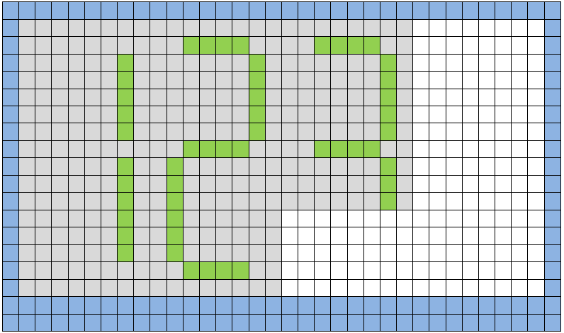
Picture1. Frame buffer implementation.
In the traditional software implementation example, digits “1” and “2” (with corresponding transparency setting) have already been printed and printing digit “3” is in progress.
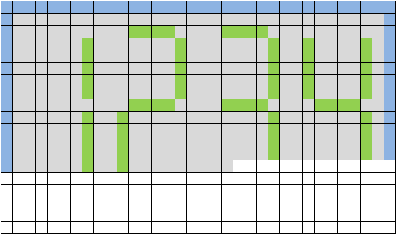
Picture 2. Streaming (online) implementation.
In this example upper part of the whole number 1234 is complete, and lower part will be complete when corresponding input pixels from sensor are processed.
Binary 8-bit digitizer
The very first attempt to implement a character generator was a binary digitizer. It was very simple and was able to display 8-bit integers at the specified screen position in binary format. A developer had to manually interpret the output, e.g. a decimal number “157” was printed as “10011101”. Below are some technical implementation details:
- Pixel counter knows when every line starts and ends (using line valid (lval) sensor signal) and counts line pixels (X screen coordinate)
- Line counter knows when each frame and each line starts and ends (using the same line valid (lval) and frame valid (fval) sensor signals) and counts frame lines (Y screen coordinate).
- Knowing text window size and offset, algorithm decides, if current pixel belongs to any of 8 printed bits and, if yes, finds out the value of the corresponding bit (“0” or “1”).
- Then, checking the pixel coordinates (x and y), algorithm finds out if it belongs to the edge of the character position (8×16 pixels).
- If “0” is to be printed and current pixel belongs to any character edge, its brightness/color is replaced with text color. Otherwise, if “1” is to be printed and current pixel belongs to right character edge its brightness/color is also replaced with text color. If both conditions are not true, pixel goes to output as is.
The module was resided in one .vhdl entity. The advantage of this implementation was its simplicity. The disadvantages were:
- Binary output (only “0”s and “1”s). It was not very convenient to use
- 8 bit limitation. To print 10-bit number it was required to instantiate module twice which would eat twice as many resources.
7-Segment hex number printer
One-digit printer
The idea of 7-segment hex printer is to implement character generator that could output hex digits like most cheap LCD displays in portable electronic devices work.
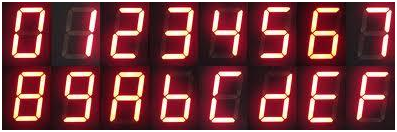
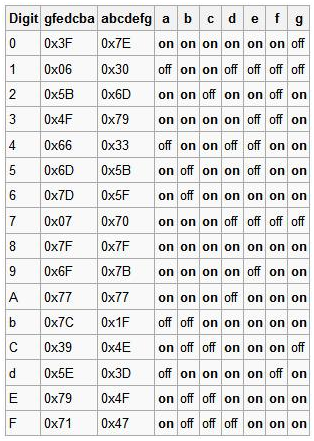
Every hex digit (0-9, a-f) is encoded into 7-bit bitmask B[0..6], where each bit controls corresponding segment. For example, as shown in the picture above, digit “8” should light all segments, so it’s bitmask is “1111111” (0x7f).
First implementation was able to output a single hex digit for given 4-bit number. The algorithm is explained in details below:
- Screen coordinates (Xs, Ys), 0 ≤ Xs < ScreenWidth, 0 ≤ Ys < ScreenHeight of current input pixel are used to find out if it belongs to a character area (8×16 pixels). If no, pixel goes to output as is
- If input pixel belongs to character position, local coordinates inside the character are calculated (Xc, Yc), 0 ≤ Xc < 8, 0 ≤ Yc < 16.
- Character local coordinates are used to find out if pixel belongs to any segment or not. If it does not, it’s brightness decreased according to transparency setting.
- If pixel belongs to a segment, its character coordinates Xc and Yc are used to get segment id S, 0 ≤ S < 6.
- Segment S is then used as an index to get “0” or “1” from input digit’s bitmask B. If it’s “1”, the brightness of the pixel increased, otherwise it’s decreased according to transparency setting.
- Resulting pixel goes to HDMI output.
Multiple-digits printer
Having one-digit hex character generator would make it possible to print any hex digit anywhere on the screen. It would be better than just binary output, but, especially when design occupies almost the whole chip, it could lead to ineffective resources (LUTs) usage – to print 32-bit integer, it would require to instantiate the hex digit printer 8 times (for each hex digit). Moreover, logic that computes segments was mostly combinational, so, in addition to extra space usage, every extra instance would negatively affect maximum design frequency (FMAX).
So, the next step was to improve hex printer to make it print hex numbers of specified width with the single instance of the printer entity.
To implement this, we designed a serializer module. Serializer takes n-bit input binary integer and index value and returns corresponding 4-bit digit. For example, for the given 11-bit input number “110’1011’1000” (0x6B8) serializer will return “0110” (0x6) for input index “0”, “1011” (0xB) for index “1” and “1000” (0x8) for index “2”.
One-digit printer used provided coordinates to print a digit at the specified location. Multiple-digits printer uses the provided location to print first digit and calculates corresponding coordinates for remaining digits.
As Picture 2 above illustrates, frame pixels arrive pixel by pixel, line by line. Multiple-digits printer module prints the input number accordingly, i.e. when pixels from first frame line arrive, the module modifies them to print first line of the whole number (not just first digit). When first image line ends, top line of all printed digits is ready. Then the second line is processed pixel by pixel, then the third, etc., until all lines are processed.
7-segment decimal printer
Although hex printer that can print any number is much better than previous binary 8-bit printer, it still not very convenient to use because it outputs numbers in hex format, while people got used to see decimal numbers. To make life easier, the Decimal printer module was designed. It uses hex printer described above, but before going there, input number is converted to the corresponding BCD representation.
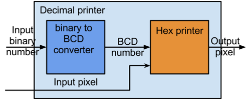
Binary to BCD converter
Binary to BCD converter converts binary numbers into corresponding packed Binary-Coded Decimal (BCD) representation. For example, number 0x0A would be converted to 0x10 and number 0xFF would become 0x255. The module uses efficient [Double dabble] algorithm.
Original version of algorithm is combinational, meaning that result of conversion is ready almost immediately. Unfortunately, for long binary inputs (e.g. 32-bit integers) it produces a lot of combinational logic which occupies significant amount of chip and dramatically decreases maximum frequency at which the design can work (FMAX). Considering the fact that during normal operation we don’t need converted BCD representation at the same clock as input binary number arrives, the algorithm was implemented in a sequential way to save FPGA area space and improve timing, produce less combinational logic and (FMAX).
Resulting algorithm is not pipelined and for n-bit input integer it produces m-bit output BCD representation in k clock cycles, here m = RoundUp(n / 3) * 4 and k = n * RoundUp(n / 3).
The Binary to BCD converter module does nothing with segments, fonts and/or pixels and can be instantiated in any context where converting from binary representation to corresponding BCD one is required and specified earlier latency is acceptable. The original (fully combinational) algorithm and description how it works can be found here. The modified version is more complex and employs a finite state machine to process each bit of input number in a sequential manner. You can download the source code of modified version here.
Character printer
Transparency setting
Next step was to implement a Character printer to be able to print anything including numbers, text or both. As you can see in the picture below, there are 3 main cases:
- A pixel does not belong to the output text window. In this case it goes to output as is. These are the pixels around the printed text.
- A pixel is inside of the output text window, but it does not belong to a character. In this case pixel brightness is altered according to the transparency setting, to make the text more readable on different backgrounds. Transparency can be turned off (in this case green letters on the green background will not be seen), or set to “no background”, when all pixels around the text will be black.
Character Generator
Functional block diagram of Character printer is presented below:
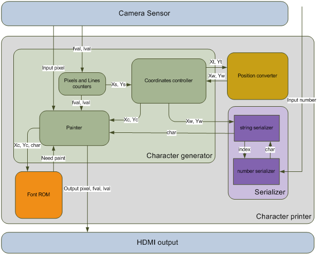
Picture 3. Functional Block Diagram of Character printer module.
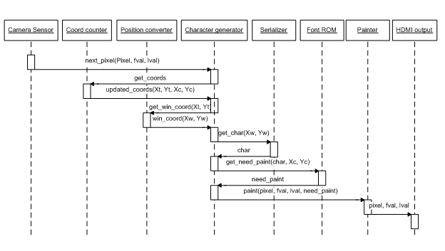
Picture 4. Sequence diagram of Character printer module.
Character generator is a main module where almost all work is done. Character generator works as follows:
- Pixel counter uses line valid signal to understand when a new line starts and counts line pixels (on-screen Xs coordinate), 0 ≤ Xs < ScreenWidth;
- Line counter uses frame valid and line valid signals to understand when a new frame and new line start and counts lines on the current frame (on-screen Ys coordinate), 0 ≤ Ys < ScreenHeight.
- Character printer uses the font size parameter, which is a scale factor from 0 to 4. Characters at scale 0 are 8×16 pixels large, scale 1 gives 16×32, scale 2 gives 32×64 pixels, etc. Using current on-screen coordinates (Xs, Ys) character generator calculates text coordinates (Xt, Yt), 0 ≤ Xt < TextColumns, 0 ≤ Yt < TextRows..
- Text coordinates are fed to position converter which generates indices for string serializer (explained in details below) to get the character code that should be printed at current position.
- Character generator also converts screen coordinates to local character coordinates (Xc, Yc), 0 ≤ Xc < 8, 0 ≤ Yc < 16.
- Local-character coordinates Xc and Yc, input character from string serializer (with data valid signal) are then fed to Font ROM module.
- Font ROM, based on given data (local character coordinates (Xc, Yc), character ASCII code and character valid), returns “1” when pixel at the given position belongs to a printed character, “0” otherwise.
- If a pixel is outside the printed text window, it goes to output as is. Otherwise, if it does not belong to a printed character, it is altered to decrease its brightness according to transparency parameter. If it belongs to a printed character, it’s replaced with text color setting.
Position converter
The main task of the position converter is to convert on-screen text coordinates (Xt, Yt) into text coordinates (indices) inside the text window (Xw, Yw), that go to String serializer module to get corresponding character from the video memory. Position converter is a very simple module made of combinational logic only.
Serializer
String serializer
String serializer contains video memory (RAM or ROM) and returns a character for requested position (Xw, Yw). If position is out of window range, it de-asserts data valid signal. In a simple text-only implementation with no placeholders for numbers, string serializer works similar to the serializer module from hex printer, but instead of returning fixed number of bits by input index, it returns character ASCII code requested by index.
Number serializer
In more complex design, message ROM would contain special placeholders for digits of one or more displayed numbers, like “%d” in C-language “printf()” function. In this case, there would be one more module instantiated, number serializer or “str”. Main function of “str” is similar to serializer module from hex printer, which used input index to extract requested 4-bit digit from longer (n-bit) input binary integer, but instead of returning binary 4-bit digit, “str” returns corresponding 8-bit ASCII code of this digit. Following the example from hex printer module, for the given 11-bit input number “110’0111’1000” (0x678) str will return 0x36 (ASCII code of character “6”) for input index “0”, 0x37 (ASCII code of character “7”) for index “1” and 0x38 (ASCII code of character “8”) for index “2”.
Part of the payoff to this developer is looking around and seeing the fruits of your Hex printer and Interpret the output e.g. a decimal number 157 was. developer have a hand in Hex printer, Interpret the output e.g. a decimal number 157 was and Character generator.
Do you have the source code of this character generator? I could really use this, or any kind of source code that do something with the HDR60…